UPDATE 2017: Controllino has removed installer and added documentation for board installation see: https://github.com/CONTROLLINO-PLC/CONTROLLINO_Library#installation-guide
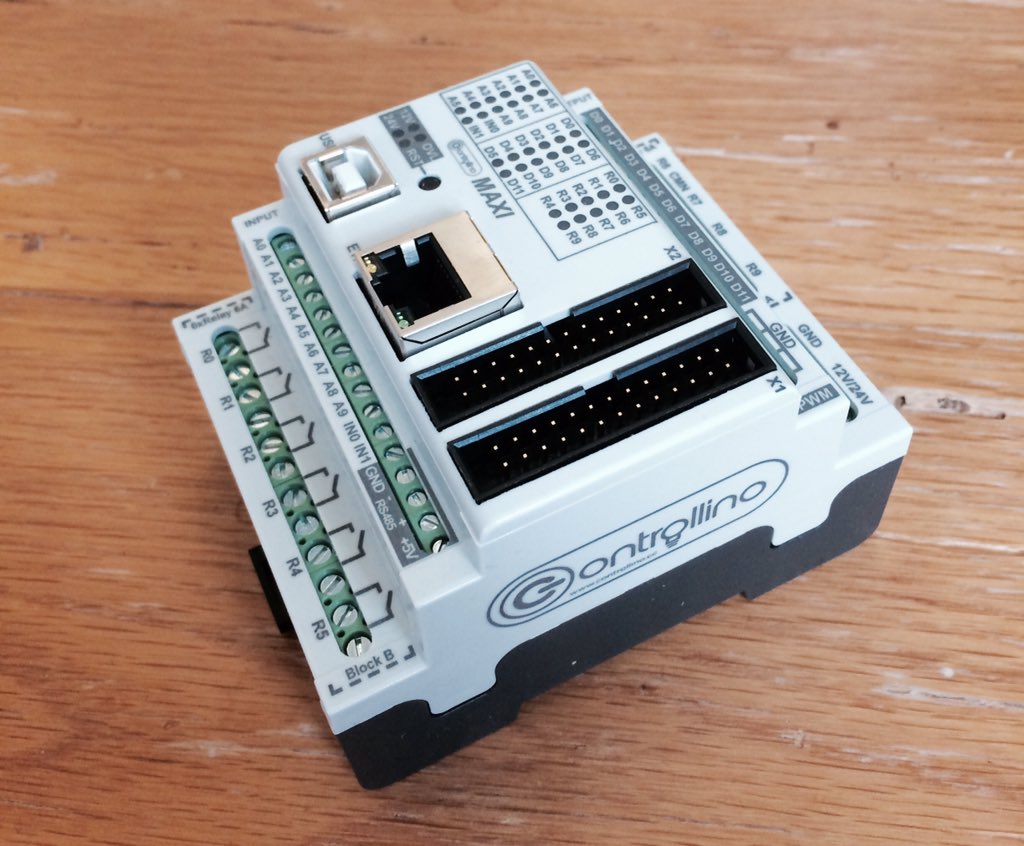
Controllino is a very new Arduino based PLC. Currently, due to how new it is, there is not much documentation.
I was very surprised to see only a Windows installer, with no info on getting up and running in Mac OSX yet.
So, here is how to do it:
Add Boards
Download & unzip the hardware files @ https://github.com/CONTROLLINO-PLC/CONTROLLINO_Library
Find the directory into which the Arduino IDE and supporting files have been installed. This may be '/usr/local/arduino' or '/usr/share/arduino' or one of many OTHER possible choices depending on your operating system. (mine was in User/{compname}/Documents/arduino )
Inside your arduino directory, if a /hardware/ folder does not exist, create it.
Drop the unzipped contents from Step 1 into hardware folder.
Add Libraries
Download & unzip the library files @ https://github.com/Controllino/ControllinoLibrary/archive/master.zip
In the same directory as the /hardware/ folder, exists /libraries/. Add the folder from inside Step 1 into libraries.
Restart Arduino IDE.
Select your Controllino Board
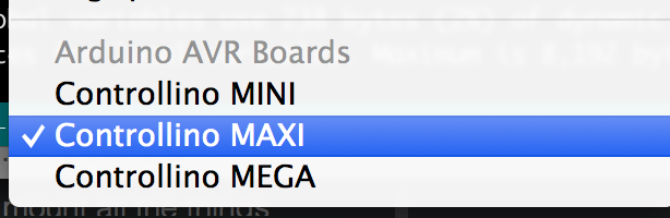
Done! Test with demo code (http://controllino.cc/wp-content/uploads/2016/01/Controllino_Example.zip)
#include <Controllino.h>
#include <SPI.h>

/*
This is basic example of arduino library use.
Any input or output can be referenced as CONTROLLINO_ and add the sign printed next to the I/O.
Remember please to install Controllino plugin before testing this sketch.
Also remember you need to select either CONTROLLINO MINI,CONTROLLINO MAXI or CONTROLLINO MEGA as your board.
*/

void setup()
{
  /* Here we prepare D0 as output and A0 as input */
  pinMode(CONTROLLINO_D0, OUTPUT);
  pinMode(CONTROLLINO_A0, INPUT);
  /* Here we initialize serial at 9600 baudrate for reporting */
  Serial.begin(9600);
  /* If we are using Controllino MEGA, we want to try using non arduino supported pins, so we initialize them */
  #ifdef CONTROLLINO_MEGA
  /* We need to set direction of all pins to output (1). We are going to use pins PD4(D20), PD5 (D21), PD6(D22) and PJ4(D23) */
  DDRD |= B01110000;
  DDRJ |= B00010000;
  #endif
  /* When using Controllino MEGA or MAXI we have acess to /OVL pin and RS458 /RE DE pins */
  #if defined(CONTROLLINO_MAXI) || defined(CONTROLLINO_MEGA)
  /* Direction for /RE (PJ5) DE (PJ6) pins is output (1). For /OLV (PE7) its input (0) */
  DDRJ |= B01100000;
  DDRE &= B01111111;
  #endif
  /* Now we report start of example */
  Serial.println("CONTROLLINO example sketch is starting now");
  DDRF &= B01111111;
}

void loop()
{
  /* We set digital output D0 to low voltage */
  digitalWrite(CONTROLLINO_D0, LOW);
  /* If we use Controllino MEGA we also set all pins PD4 (D20), PD5 (D21), PD6(D22) and PJ4(D23) to low as well */
  #ifdef CONTROLLINO_MEGA
  PORTD &= B10001111;
  PORTJ &= B11101111;
  #endif
  /* With Controllino MEGA or MAXI we set /RE (PJ5) and DE (PJ6) pins to low. Also we read out the /OVL (PE7) and print it out */
  #if defined(CONTROLLINO_MAXI) || defined(CONTROLLINO_MEGA)
  PORTJ &= B10011111;
  Serial.print("/OVL: ");
  Serial.println(PINE >> 7);
  #endif
  /* Now we read out the voltage on Analog input A0 and report it */
  Serial.print("A0: ");
  Serial.println(analogRead(CONTROLLINO_A0));
  /* We wait one second (1000 ms) and repeat the process */
  delay(1000);
  /* We set digital output D0 to high voltage now */
  digitalWrite(CONTROLLINO_D0, HIGH);
  /* If we use Controllino MEGA we also set all pins PD4 (D20), PD5 (D21), PD6(D22) and PJ4(D23) to high as well */
  #ifdef CONTROLLINO_MEGA
  PORTD |= B01110000;
  PORTJ |= B00010000;
  #endif
  /* With Controllino MEGA or MAXI we set /RE (PJ5) and DE (PJ6) pins to high. Also we read out the /OVL (PE7) and print it out */
  #if defined(CONTROLLINO_MAXI) || defined(CONTROLLINO_MEGA)
  PORTJ |= B01100000;
  Serial.print("/OVL: ");
  Serial.println(PINE >> 7);
  #endif
  /* And again we read out the voltage on Analog input A0 and report it */
  Serial.print("A0: ");
  Serial.println(analogRead(CONTROLLINO_A0));
  /* At least we wait again one second and let the loop repeat itself */
  delay(1000);
}